The request
ok I want to study a new project, that project is a "box" in which there is a smoothieboard v2-core (without the stepper drivers), and it's a metal box with screw terminals all arund it, and people can wire it into their cnc mill or cnc lathe or other types of machines, wiring it to their stepper motor drivers or servo drivers, and spindle driver, etc etc. now the big thing I need to know to prepare this, is the "pinout" the name and types of connections inside those machines people would be rewiring using our stuff, like a tormarch, or an old mach3 machine, or other controllers/machine types we'd be a drop-in replacement for. so what I need you to find for me is as many (if possible MANY) different machines (let's concentrate on cnc mills, lathes, pen plotters, and lasers, for now), and for each find the name of their connecitons/wires, their "pinout" essentially, so we could contruct for each machine a big "sticker" we'd stick on top of our metal box (that contains the smoothieboard v2-core) so it's trivial for people to "wire into" their machine. please for now just find MANY different machines and their pinouts, and save those to src/docs/ in a html doc, with diagrams and any images you found from your source, and links, and visual elements and tables and anything else you think would be useful to document or figure out the wiring and to prepare the creation of our stickers and our "boxes".
Request transcript: /home/arthur/.codex/sessions/2026/09/23/rollout-2026-09-23T02-58-07-01a0cbc5-19d8-7d00-a737-6725e9cab16f.jsonl
Do not wire from this survey. A screw-terminal sticker cannot safely be finalized until the machine serial/revision, installed control board, V2-Core production schematic, interface ratings, and safety-chain design are known. This page records research facts and gaps; it is not an installation guide, electrical design, or safety certification.
What the sources support
DB25 maps existTormach publishes distinct connector profiles for PCNC 440, older PCNC 770/1100, and 15L Slant-PRO. They are not the same map.
Some maps are internalSeveral newer Tormach machines publish cabinet schematics and wire tables, but not a universal external controller port. Their serial/control variant matters.
V2-Core is unresolvedChecked-in V2 material does not establish a production Core screw-terminal map or complete external-driver ratings. No final Core-side label is justified yet.
Machine-side connector maps found
Tormach 770M / 1100M · internal J6 map is a restricted-source lead
The official machine-control-board pages identify separate drawings for 770M and 1100M, each with a “Stepper Control Cable Pin Assignments” chart at J6. The 1100M drawing is 37158 Rev I, sheet 5 of 12; the 770M drawing is 37361 Rev J, sheet 5 of 12. Both title blocks mark the drawings proprietary/confidential and state that the drawings and information may not be copied, used, or disclosed without prior written permission. This survey links the source pages but does not reproduce or transcribe their internal pin assignments. Obtain written permission or a separately authorized source before adding those maps.
Sources: Tormach 1100M Machine Control Board and 770M Machine Control Board. The linked pages show machine-specific internal ribbon/board connections, not a universal retrofit port.
Tormach PCNC 440 · DB25 J4/J10 to IDC26
The official article separates the PCNC 440 from the PCNC 770/1100 and 15L tables. It says the machine-side DB25 connects through a ribbon cable to IDC26 at the machine control board or MX3660. The table preserves published function labels; missing electrical characteristics stay unknown.
PCNC 440 DB25 connector, pins 1–17
| Pin | Source function label | Electrical details | Sticker evidence |
|---|
| 1 | Spindle Enable | Level, polarity, current, isolation unknown | Function known |
| 2 | X Step | Unknown | Function known |
| 3 | X Direction | Unknown | Function known |
| 4 | Y Step | Unknown | Function known |
| 5 | Y Direction | Unknown | Function known |
| 6 | Z Step | Unknown | Function known |
| 7 | Z Direction | Unknown | Function known |
| 8 | A Step | Unknown | Function known |
| 9 | A Direction | Unknown | Function known |
| 10 | X Limit; source notes it is used for enclosure door switch | Unknown | Door/limit behavior needs machine check |
| 11 | Y Limit | Unknown | Function known |
| 12 | Z Limit | Unknown | Function known |
| 13 | Probe In | Unknown | Function known |
| 14 | Spindle Speed | Unknown | Function known |
| 15 | Estop Reset | Unknown; not evidence of a safety-rated E-stop path | Function known, safety design unresolved |
| 16 | Charge Pump | Unknown | Function known |
| 17 | Coolant | Unknown | Function known |
| 18–25 | Not described in this machine table | Do not infer ground or NC | Not mapped by this source |
Source: Tormach, “DB25 Cable J4 and J10(440) Pinout”, PCNC 440 section. Its same page calls the link “serial communication” while documenting step/dir and I/O functions; confirm the installed cabinet and controller. A separate PCNC 440 electrical schematic is also available.
Older Tormach PCNC 770 and PCNC 1100 · shared published DB25 table
Tormach publishes a separate PCNC 1100/770 section. Several voltage observations appear, but the labels do not establish a conventional step/direction interpretation for pins 2–9. Record them literally until the exact controller revision and electrical interface are verified.
Published PCNC 770/1100 DB25 labels and observations
| Pin(s) | Source label / observation | Open issue |
|---|
| 1 | Speed/Enable; 2.5 VDC measured, 0–10 kHz | Waveform, logic threshold, common, isolation unknown |
| 2 | X-Axis Direction — “0 Vdc (Normal) and X+, 5 Vdc X-” | Source wording does not clearly associate each voltage/state; circuit type unknown |
| 3 | X+/- — “5 Vdc (Normal), 4.75 Vdc (Pressed)” | Not identified as step pulses; circuit and polarity unknown |
| 4 | Y-Axis Direction — “0 Vdc (Normal) and Y+, 5 Vdc X-” | Source literally says “X-” here; possible source error, do not silently correct |
| 5 | Y+/- — “5 Vdc (Normal), 4.75 Vdc (Pressed)” | Not identified as step pulses; circuit and polarity unknown |
| 6 | Z-Axis Direction — “0 Vdc (Normal) and Z+, 5 Vdc X-” | Source literally says “X-” here; possible source error, do not silently correct |
| 7 | Z+/- — “5 Vdc (Normal), 4.75 Vdc (Pressed)” | Not identified as step pulses; circuit and polarity unknown |
| 8 | A-Axis Direction — “0 Vdc (Normal) and A+, 5 Vdc X-” | Source literally says “X-” here; possible source error, do not silently correct |
| 9 | A+/- — “5 Vdc (Normal), 4.75 Vdc (Pressed)” | Not identified as step pulses; circuit and polarity unknown |
| 10–12 | X, Y, Z Limit; source says 5 VDC | Range, source/sink, common, protection unknown |
| 13 | Accessory Input | Function/electrical type unknown |
| 14 | Coolant; source says 5 VDC | Polarity/current/output stage unknown |
| 15 | Machine OK | Polarity/electrical type unknown |
| 16 | FWD 5 V / REV 0 V | Direction encoding/reference unknown |
| 17–25 | Not described in this table | Unknown; do not infer NC or ground |
Source: PCNC 770 and PCNC 1100 sections of the Tormach DB25 pinout page. Keep the 770 and 1100 as separate records even though the article groups them; confirm serial, control board, and connector revision.
Tormach 15L Slant-PRO · separate lathe DB25 map with explicit uncertainty
Published 15L Slant-PRO DB25 labels
| Pin(s) | Source label / observation | Open issue |
|---|
| 1 | Speed/Enable; 2.5 VDC measured, 0–10 kHz | Ratings and function boundary unknown |
| 2 | X-Axis Direction — “0 Vdc (Normal) and X+, 5 Vdc X-” | Source wording/state unclear; circuit type unknown |
| 3 | X+/- — “5 Vdc (Normal), 4.75 Vdc (Pressed)” | Not identified as step pulses |
| 4 | Z-Axis Direction — “0 Vdc (Normal) and Z+, 5 Vdc X-” | Source literally says “X-”; possible source error |
| 5 | Z+/- — “5 Vdc (Normal), 4.75 Vdc (Pressed)” | Not identified as step pulses |
| 6 | Spindle Dir | Level, polarity, common unknown |
| 7–9 | ATC turret switch input; ATC forward; collet closer | Electrical types and kit/revision coverage unknown |
| 10–12 | Z, A, B Encoder | Quadrature wiring, levels, phases unknown |
| 13 | Accessory Input | Unknown |
| 14 | Coolant; source adds a question mark to its 5 V measurement | Unverified |
| 15 | Machine OK | Electrical type unknown |
| 16 | Frequency-encoded data input; source adds “??” before a possible FWD/REV interpretation | Explicitly unresolved by source |
| 17–25 | Not described in this table | Unknown |
Sources: Tormach DB25 page, “15L Slant Pro” section and 15L electrical schematic index. The schematic is internal; the DB25 article leaves some claims explicitly uncertain.
Sherline 8760 4-axis driver box · DB25 control interface
Sherline publishes the driver-box DB25 map and timing/logic statements. It is the PC-to-driver-box control connector, not a motor-phase connector. The 5-pin DIN motor ports are separate; the retrieved product page does not define the full pin-to-winding table.
Sherline 8760 DB25 functions from its product page
| Pin | Published function | Pin | Published function |
|---|
| 1 | Input from LinuxCNC (may be ignored by other systems) | 14 | Input from LinuxCNC, C1 |
| 2 | X Direction | 15 | Not specified on retrieved page |
| 3 | X Step | 16 | Input from LinuxCNC, C2 |
| 4 | Y Direction | 17 | NC |
| 5 | Y Step | 18–25 | Ground |
| 6 | Z Direction | 10 | NC |
| 7 | Z Step | 11 | Output to LinuxCNC |
| 8 | A Direction | 12 | Output to LinuxCNC, XYZ home |
| 9 | A Step | 13 | NC |
Known from Sherline: logic high must exceed 2 V; logic low must be below 0.5 V; step pulses are active-low and at least 22 μs long. These are 8760 facts, not assumptions for another box or bare motor.
Source: Sherline 4-Axis CNC Driver Box product page, DB25 and parameters sections. It also states 24 VDC/4 A for the driver-box power system; this is not a DB25 signal rating.
Sherline Acorn 9400 → 8760 mill/lathe configurations
The 8760 has the documented DB25 pin roles; Acorn H6 output pins must be remapped in CNC12 to those DB25 roles. The pin column below is the resulting cable/8760-side DB25 assignment, while the axis column is the software configuration. These are paired controller profiles, not additional machine-side connector families.
Mill configuration from Sherline’s Acorn remapping guide
| Configured Acorn axis | Acorn DB25 pin roles after custom remap | 8760 DB25 receiver roles | Configuration note |
|---|
| Axis 1 (X) | 2 = Direction 1; 3 = Step 1 | 2 = X Direction; 3 = X Step | Custom remap is required; verify current CNC12 setup |
| Axis 2 (Y) | 4 = Direction 2; 5 = Step 2 | 4 = Y Direction; 5 = Y Step | Mill configuration |
| Axis 3 (Z) | 6 = Direction 3; 7 = Step 3 | 6 = Z Direction; 7 = Z Step | Mill configuration |
| Axis 4 (A) | 8 = Direction 4; 9 = Step 4 | 8 = A Direction; 9 = A Step | Mill configuration |
Lathe configuration from Sherline’s Acorn remapping guide
| Configured Acorn axis | Acorn DB25 pin roles after custom remap | 8760 DB25 receiver roles | Configuration note |
|---|
| Axis 1 (Z) | 2 = Direction 1; 3 = Step 1 | 2 = X Direction; 3 = X Step | Acorn Z is assigned to the 8760’s X input channel; confirm downstream lathe-axis wiring |
| Axis 2 (X) | 4 = Direction 2; 5 = Step 2 | 4 = Y Direction; 5 = Y Step | Acorn X is assigned to the 8760’s Y input channel; confirm downstream lathe-axis wiring |
Sherline’s lathe guide explicitly says pins 4 and 5 of the 8760 mapping are not used in this application, yet its later axis instructions assign the lathe’s Axis 2 (X) to pins 4 and 5. Preserve that apparent document inconsistency and confirm the exact setup before wiring.
Sources: Sherline/Acorn controller, Acorn-to-8760 DB25 diagram, and Configure Acorn for Sherline. Read the active CNC12 remap before using these roles.
Controller interfaces useful as reference profiles
GeckoDrive G540 Rev 8 · DB25, screw terminal block, motor DB9
The G540 combines a motion interface with four stepper drives. Its map helps identify a G540 retrofit but is not the machine’s OEM wiring. Motor DB9 connectors carry motor-phase outputs and stay separate from the DB25 logic connector.
G540 Rev 8 DB25 pin function summary
| Pin group | Published function |
|---|
| 1 | Output 2 |
| 2–9 | X Step, X Direction, Y Step, Y Direction, Z Step, Z Direction, A Step, A Direction |
| 10–13 | Inputs 1–4 |
| 14 | VFD PWM (manual labels it 50 Hz) |
| 15 | Fault (input to PC) |
| 16 | Charge Pump (>10 kHz) |
| 17 | Output 1 |
| 18–25 | GND |
Sources: Geckodrive G540 Manual Rev 8 and Geckodrive manual index. Rev 8 also maps the main terminal block and motor DB9 connectors. It describes opto-isolation for LPT signals; verify the external driver’s actual interface requirements.
Mesa 7I96S · pluggable screw-terminal motion interface
The Mesa manual names step and direction pairs on screw terminals. This is a controller-side connector map, not evidence that a target machine uses those electrical conventions.
7I96S TB1 connector, manual pages 8–9
| TB1 pins | Signal | TB1 pins | Signal |
|---|
| 1 | GND | 13 | GND |
| 2–5 | STEP0−, STEP0+, DIR0−, DIR0+ | 14–17 | STEP2−, STEP2+, DIR2−, DIR2+ |
| 6 | +5VP | 18 | +5VP |
| 7 | GND | 19 | GND |
| 8–11 | STEP1−, STEP1+, DIR1−, DIR1+ | 20–23 | STEP3−, STEP3+, DIR3−, DIR3+ |
| 12 | +5VP | 24 | +5VP |
TB3 domain: manual says 11 isolated 5–36 V inputs, four isolated high-current DC outputs, and two high-isolation AC/DC outputs. Do not infer output current or AC rating from the summary; use the exact manual and hardware revision.
Source: Mesa 7I96S manual, connector pages 8–11. It describes +5VP field pins as PTC short-circuit protected 5 V outputs.
Mach3 / parallel-port installs · configurable pin roles
Mach3 is software, not a machine wiring standard. A machine with a DB25 may use a PC port, external motion controller, breakout board, G540, or another controller. LinuxCNC’s official parallel-port guide likewise makes pin direction depend on port mode and permits output inversion; its stepper example is one configurable assignment.
Sticker rule: label a DB25 role only after identifying the installed controller/breakout and reading its active configuration. Connector numbering alone does not reveal the assigned axis, limit, spindle, or safety role.
Other controller references
- CNC4PC C11G Rev 9.3: DB25 pins 1–9 buffered outputs; 10, 11, 12, 13, 15 dedicated inputs; 14, 16, 17 outputs with assignments dependent on use/jumpers. Published input range 2–5 V; output maximum +5.5 V and typical current 24 mA. C11G I/O specifications and pinout.
- Warp9 Ethernet SmoothStepper Rev 2: three 26-pin parallel-style headers using DB25-style numbering; direct interface maximum 5 V and the vendor expects a breakout board for machine wiring. ESS documentation.
- Centroid Acorn Rev 3/4: vendor connector schematics and revision-specific maps are available; machine assignments depend on hookup schematic and setup. The quick-start document says DIY hookup examples are incomplete educational examples. Acorn Start Here, Centroid schematic browser, and Acorn Rev 3 specification manual.
Laser controller and machine-side findings
Ruida RDC6445G / RDC6445S · controller map, not universal machine wiring
The Ruida manual publishes a useful control-card map and distinguishes glass-tube and RF laser uses for the same pins. It does not prove which PSU, door circuit, water protection, or safety-chain arrangement is installed in a particular cutter.
RDC6445G/S V1.2 CN5 first laser interface, manual page 17
| Pin | Label | Published role | Variant note |
|---|
| 1 | GND | Power ground output | Match against exact PSU domain |
| 2 | L-ON1 | Laser-enable control | RF laser: unused; glass-tube use depends on PSU logic |
| 3 | LPWM1 | Laser power control | RF laser: RF-PWM; glass tube: PSU PWM input |
| 4 | WP1 | Water-protector input | Preserve configured interlock behavior |
Axis connectors label pin 1 DIR (open-collector output), pin 2 PUL (open-collector output), and pin 3 +5V output. The manual says direction polarity and pulse edge are configurable and that pulse/direction require common-anode connection at the motor driver. It does not make the rest of the cabinet wiring universal.
Source: Ruida RDC6445G Control System V1.2 Manual, axis connector description and §4.10 CN5/CN6. Confirm controller suffix/revision and actual PSU model.
K40-style blue-box laser · MYJG40W PSU example, older community wiring record
The repository’s SmoothK40 guide describes one MYJG40W example and explicitly says PSU models and terminal labels vary; the author could not find a manual for that particular supply. It records labels including L−, FG, AC, G, P/WP, L/TL, IN, 5V, and +24V, plus one X/Y/limit harness variant. This is secondary, model-variable evidence, not a manufacturer pinout.
Repository sources: SmoothK40 guide and Blue-box PSU guide. They describe more than one laser-fire arrangement and warn about 3.3 V control outputs requiring a suitable interface for 5 V input hardware. Treat these labels as leads until the exact PSU diagram and machine revision are found.
Makerbase MKS DLC32 V2.1 · desktop diode-laser controller
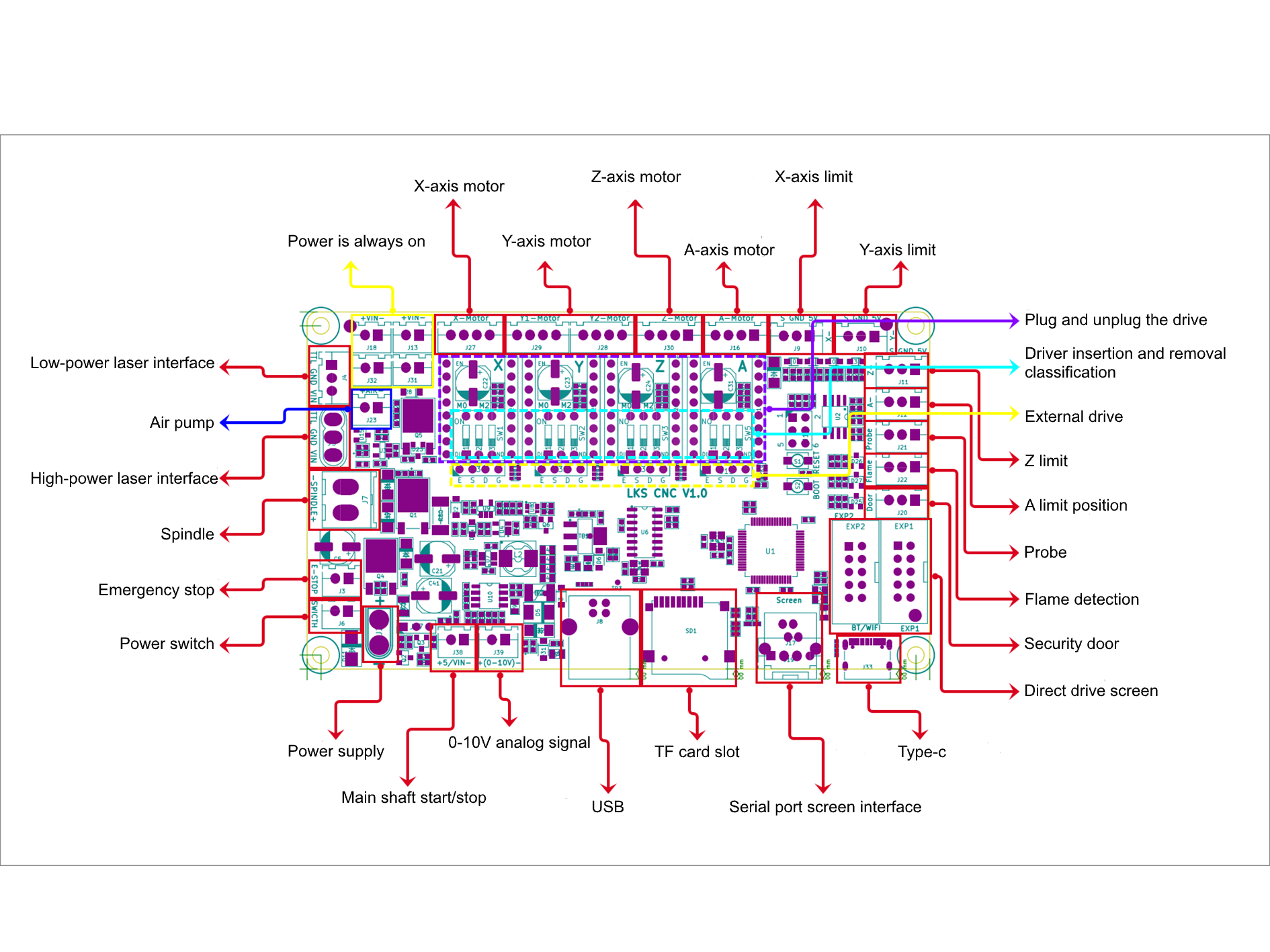
Makerbase documents a configurable engraving controller and firmware profile. Its official wiki labels an air/cold-water-assist control SCL and describes 3.3 V/0 V high/low states; it also says higher-power laser PSUs require a separate supply, common ground, and TTL signal. The project README points to a wiring manual that returns 404 at the audited URL, so a complete connector map remains unavailable.
Ortur Laser Master 3 · closed machine harness

Ortur identifies the OLM-ESP-PRO-V2.4 motherboard, NEMA 17 motors, 24 V power system, and safety features including key lock, E-stop, exposure timer, tilt detection, USB monitoring, and position protection. Public support material found here does not provide external motor-driver connector pinouts. Treat it as an internal-rewire case; preserve the machine interlocks.
Source: Ortur Laser Master 3 support page. No external step/dir or PSU terminal map was found there.
Plotters
Pen plotter connection evidence
| Product/configuration | Source-backed connections | Sticker assessment |
|---|
| AxiDraw V2/V3/SE/A4, V3/A3, XLX, MiniKit, SE/A1, SE/A2, V3/B6 | Official API exposes USB serial and EBB firmware. Standard pen-lift servo uses B1; optional narrow-band brushless servo uses B2. XY stepper signals are internal. | Internal / USB serial No exposed machine-side step/dir map. These model variants do not constitute seven pinout maps. |
| Makeblock XY Plotter V2.0 | Official project describes Me baseboard, USB connection, Arduino Leonardo firmware, and serial/G-code application. Retrieved official material does not show external-driver terminal pinouts. | Internal only Identify board revision before replacing drivers. |
Candidate inventory · 25 assessed configurations
“Configuration” is intentional: some of the strongest public maps describe a control board rather than an OEM cabinet. This survey does not claim each row can be converted safely or that every row has a useful machine sticker.
Open the full inventory and evidence status
| Category | Exact scope | Evidence found | Classification | Sticker readiness |
|---|
| CNC mill | Tormach PCNC 440, DB25 J4/J10 | Machine pins 1–17; inside cabinet IDC26 to machine board/MX3660 | Direct DB25 map | Functions known; ratings/serial applicability required |
| CNC mill | Tormach PCNC 770 legacy | Shared 770/1100 DB25 observations, some labels unclear | Direct but ambiguous | Not ready |
| CNC mill | Tormach PCNC 1100 legacy | Same source table; keep separate machine record | Direct but ambiguous | Not ready |
| CNC mill | Tormach 770M | J6 stepper-control assignment chart on 37361 Rev J, sheet 5/12; drawing marked proprietary/confidential | Restricted source lead | No transcription without written permission or another authorized source |
| CNC mill | Tormach 770MX, MF/MH serial scope | Official subsystem schematics and wire table | Internal schematic | Cabinet-specific; source drawing marked proprietary |
| CNC mill | Tormach 1100M | J6 stepper-control assignment chart on 37158 Rev I, sheet 5/12; drawing marked proprietary/confidential | Restricted source lead | No transcription without written permission or another authorized source |
| CNC mill | Tormach 1100MX | Official subsystem schematics and wire table | Internal schematic | Cabinet/revision-specific |
| CNC lathe | Tormach 8L, serial LA10506+ | Current official schematics and terminal strips; older serials use TD10829; check drawing rights before transcribing | Internal / serial split | Resolve serial and reuse permission before mapping |
| CNC lathe | Tormach 15L Slant-PRO | DB25 table plus separate electrical schematic index; “?” labels remain | DB25 with gaps | Verify uncertain pins first |
| CNC mill | Sherline CNC-ready mill + 8760 | Manufacturer DB25 map, logic thresholds and step timing | Driver-box map | 8760-specific; motor DIN separate |
| CNC lathe | Sherline CNC-ready lathe + 8760 | Same 8760 connector; lathe axes/spindle use separate config | Driver-box map | Configuration-specific insert |
| CNC mill | Sherline/Acorn 9400 → 8760 mill | Official crossover/remap diagram and mill config guide | Configurable DB25 | Read active CNC12 map |
| CNC lathe | Sherline/Acorn 9400 → 8760 lathe | Lathe mapping changes axis-channel assignments | Configurable DB25 | Read active CNC12 map |
| Control reference | Generic Mach3 + PC parallel port | Manual provides setup examples; software pin roles configurable | Configurable | No machine profile without BOB and active config |
| Driver/controller | GeckoDrive G540, Rev 8 manual | DB25, terminal block, DB9 motor connector maps | Controller map | Only if exact integrated driver is present |
| Breakout board | CNC4PC C11G, Rev 9.3 | DB25 I/O groups, TTL levels, pull direction and jumpers | Board map | Record jumper state |
| Motion controller | Warp9 ESS, Rev 2 | Three 26-pin parallel-style ports; DB25 numbering and 5 V limit | Host interface | Machine map is BOB/config dependent |
| Motion controller | Mesa Electronics 7I96S | TB1/TB2 step-dir/encoder; TB3 isolated 5–36 V input range | Controller terminal map | Not OEM machine wiring |
| Motion controller | Centroid Acorn Rev 3/4 | Vendor connector schematics and revision-specific maps | Revision/config dependent | Use exact manual and hookup schematic |
| CO₂ laser | K40-style blue box + MYJG40W example | Repo guide records PSU labels and one harness variant | Secondary / variable | Need exact PSU manufacturer sheet |
| CO₂ laser control | Ruida RDC6445G/S, V1.2 | Axis OC output and CN5/CN6 control pins; tube-type differences | Controller map | Machine PSU and safety remain specific |
| Diode laser control | Makerbase MKS DLC32 V2.1 | Wiki/firmware evidence; linked wiring PDF currently 404 | Partial / source gap | Need board schematic and manual |
| Diode laser | Ortur Laser Master 3, OLM-ESP-PRO-V2.4 | Board, motor class, supply family, safety functions | Closed/internal | No public external terminal map found |
| Pen plotter | AxiDraw model family, EBB controller | USB serial and B1/B2 servo control | Internal / USB serial | No external step/dir map |
| Pen plotter | Makeblock XY Plotter V2.0 | Official firmware/USB instructions, no external driver map | Internal only | Need exact board-level evidence |
V2-Core label gate
The machine source may provide a function name, but a printable adapter sticker must also describe what the V2-Core screw terminal accepts or drives. The required Core-side contract is not established by the checked-in sources reviewed for this survey.
Board identity
Freeze Core PCB revision, assembly options, and connector/reference designators.
STEP/DIR/ENABLE
Verify pins, pulse limits, voltage/current, reset state, protection, and populated buffers.
Inputs
For limits/probe/encoder, verify range, polarity, pulls, filtering, isolation, and common.
Analog/PWM
Distinguish logic PWM from rated 0–10 V spindle reference; verify scaling, frequency, isolation, fault state.
Safety
Document independent E-stop and machine safety chain; preserve door, water, key, and laser interlocks.
Power domains
Separate logic, field supply, driver DC bus, spindle output, mains, chassis bond, and PE.
Repository starting points: V2 Prime documentation, V2 schematic, STM32H7 pin usage, and historical V2 Kickstarter updates. Prime docs and schematic disagree on some header/probe details; the production Core map remains unverified. The pin-usage document identifies unbuffered ADC inputs with a 3.3 V ceiling; do not generalize that to every other Core I/O.
Sticker record template
Require these fields before promoting a candidate to a printable adapter label. “Unknown” is an explicit value; blank cells are not evidence.
| Field | Required record | Example |
|---|
| Applicability | Machine model, serial range, control generation, board revision | PCNC 440; DB25 J4/J10 source; serial scope to confirm |
| Physical endpoint | Connector ref, view/orientation, pin, mating side | DB25 machine-side pin 2 |
| Signal | Literal source label, direction, polarity, active state, waveform | “X Step”; other details unknown |
| Electrical contract | Voltage, current, sink/source, common, isolation, protection | Unknown until schematic/manual/measurement |
| Wire identity | Wire number/color, cable/pair/shield, original termination | Unknown in DB25 article |
| Core endpoint | Exact Core terminal, direction, rating, protection, interface needed | Unknown pending production design |
| Safety boundary | E-stop, limits, guards, interlocks, inhibit behavior | Verify against exact machine schematic |
| Evidence | Source, revision/date, page/section/figure/table, access date | Linked beside each profile |
Next research order
- Obtain the released V2-Core production schematic and derive every connector’s electrical limits.
- For restricted Tormach drawings, obtain written permission or an independently authorized source before transcribing internal maps; obtain the 8L TD10829 serial-specific document and verify uncertain 15L pins.
- Find primary schematics/service docs for more mill and lathe controller generations. Record gated OEM interfaces as evidence gaps rather than importing unrelated legacy maps.
- For lasers, add exact PSU/controller/machine combinations and keep machine, controller, PSU, tube/module, and safety options separate.
- For plotters, prioritize products with documented external-driver or accessory connectors. Keep USB-only products with no board map classified as internal/closed.
- Promote no sticker to production until source and machine harness agree pin-by-pin and Core-side ratings have been reviewed.
Scope, evidence rules, and exclusions
- Manufacturer/controller manuals, support pages, schematics, and repositories were preferred. K40 MYJG40W notes are older repository-authored secondary material.
- Configuration examples are not machine standards. DB25/26 numbering does not determine axis, limit, spindle, or E-stop roles.
- Internal cabinet wiring does not imply a plug-compatible retrofit port.
- No mains, spindle output power, laser high-voltage, or motor-phase wiring recipe is provided.
- Some Tormach drawing pages contain a proprietary/confidential notice restricting reproduction and use of the contained information without prior written permission. This page links to those sources but does not copy their images or transcribe their restricted maps.
- The source page is stored in
src/docs as requested. The separate research preview at smoothie-box-pinout-research.pages.dev republishes edits automatically; this is not part of the Jekyll documentation site.
Source register
External sources were accessed 2026-09-23. Links are reference citations; HTML, CSS, JavaScript, and SVG diagrams have no remote loading dependencies.